3. Path creation(2)

We will explain the operation procedure for creating a path for RobotWorks.

a. Face

ツール面直

Figure-12 Tool face

面のエッジは閉曲線

Fig. 13 The edge of the face is a closed curve

Conditions

  • The tool works straightforwardly. (Fig.-12)
  • The edge of the glued face of the oil pan is a closed curve. (Fig.-13)
  • パス
    パス

    Operation procedure

    Operation procedure : The operation procedure can automatically create a path by just clicking the figure twice.

  • Select a tool (click the shape or select it from the tree.
  • Select the ridgeline of the target face. (Fig.-14)
  • Select the target face. (Fig. 15)
     (Since the selected face row is closed, the graphic element to be clicked is over.)
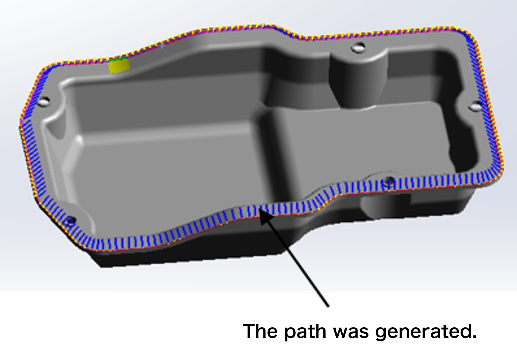
  • The path has been created. (Fig. 16)

  • 稜線の選択

    Figure-14 Ridge selection

    面の選択

    Figure-15 Selection of faces

    パス作成

    Figure-16 Path creation


    b. edge

    Conditions

    ①The tool works straightforwardly.

    ②The ridgeline is a closed curve.


    Operation procedure

    Operation procedure : The operation procedure can automatically create a path by just clicking the figure three times.

  • Select a tool.
  • Select the surface of the target edge (ridge line). (Fig.-17)
  • Select the target edge. (Fig.-18)
    Select the final point. (Fig.-19)
  • The path has been created. (Fig.-20)
  • The path created above interferes with the side wall.
     Use fanl points to avoid it. (Fig. 21)
  • A path that does not interfere with the side wall has been created. (Fig.-22)

  • 面の選択

    Figure 17 Face selection

    エッジの選択

    Figure-18 Edge selection

    最終点の選択

    Figure19 Selection of final point

    パス作成

    Figure 20 Creating a path

    ファンルポイント

    Figure 21 Funal Point

    干渉しないパス

    Figure 22 Non-interfering path


    c. Pattern

    エッジの選択

    Figure 23, edge selection

    エッジの選択

    Figure 24 Face, edge selection

    Conditions

    ①The tool works straightforwardly.

    ②The ridgeline is a closed curve.


    Operation procedure

    Operation procedure : The operation procedure can automatically create a path by just clicking the figure three times.

  • Select the face on which you want to create a path. (Fig. 23)
  • Select the edges of the opposing faces. (Fig. 24)
  • Set the parameters. (Fig. 25)
  • Determine the midpoint you want to create between the two edges (5 in Figure-26).
  • Select the face for which you want to create a path.
  • f you want to create more pass points in the extension of the original surface (up / down: left / right), enter the extension length (mm) in "pre" and "post".
  • The path has been created. (Fig. 26)
  • Passpoints have been created up, down, left and right. (Fig. 27)

  • パターンリードのパラメーター

    Figure 25 Pattern read parameters

    パス作成

    Figure-26 Path creation

    延長されたパス

    Figure-27 Extended path